Testing
The testing required checking the clearance between the blades, the rpm of the blades, which ensures synergy with the rest of the device, and the material output of the device for the desired fiber size. The main goal that the device must meet in testing is producing appropriately sized fibers.
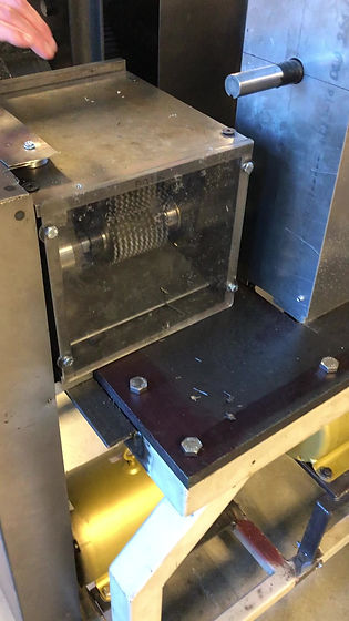
Test 1: Blade Clearance
The method of testing the blade clearance was securing the blades in the location where they would be used, and then measuring between the blades.
The distance between the blades was difficult to directly measure. Due to the blades being recessed in the housing, a caliper could not fit inside to measure the inside distance. For the first test, stacks of paper were inserted between the blades until no more could fit, and then a measurement was taken of the thickness of the paper. The distance between blades was estimated to be the width of a spacer minus the width of a blade taken in half, or 31 thousandths of an inch. Measured from the blades on the lower shaft, the distance to the next blade left was measured to be 34 thousandths, and to the right was 23 thousandths. The difference likely stems from the spacers between each blade bank and the housing slightly differing in width as machined. However, the clearance is high enough that the machine can be run. Due to the inaccuracy of using paper, which can be bent or compressed, another test will be administered using a clearance gauge when one becomes available.
 |  |  |
|---|---|---|
 |  |

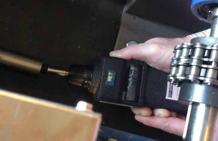
Test 2: Shaft RPM
Blade RPM was tested by using a contact tachometer pressed against the end of one of the blade shafts.
The test proceeded as anticipated. The only difficulty was getting the tachometer tip at the very center of the shaft and holding it with the correct amount of pressure to keep it on. This difficulty in holding the tachometer on lead to a difficulty in obtaining a steady measurement, but the reading leveled out at around 620 rpm. This value was very close to the calculated value of 613 rpm. However, the test was considered a fail because the required rpm for the test to be successful was much lower, at 9.6 rpm.

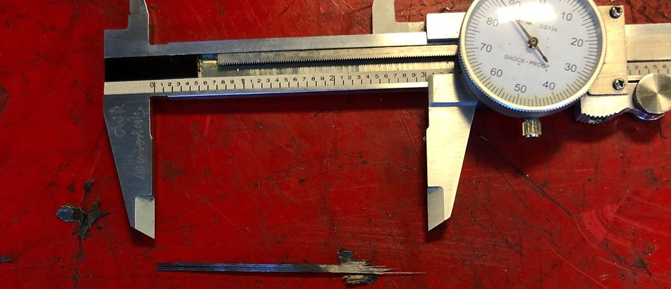
Test 3: Chip Size
The method of testing chip size will be running crushed composite strips through the shredder blades and measuring the fiber length in the resulting chips.
The test proceeded as planned, with the exception of the entire device being operational. The crushing wheels on the device were not functioning properly at the time of testing, so the strips were fed manually into the cutters using pliers and clamps to deliver and secure them. The resulting fibers came out in smaller chunks than expected, they were thoroughly shredded instead of cut into chips as predicted. This did not effect the testing result directly, as the fibers could still be measured in this form.
Testing Summary
The spaces between the blades were 0.034 and 0.023 inches, on either side. The goal was that there be a retained clearance on either side, so the test was a success. This test represents the ability for the blades to run at speed without wearing or binding on each other.
The blade rpm was 620, +/- 5 rpm and the accuracy of the tachometer, which is considerably greater than the 9.6 rpm required. The test was a fail because the rpm is much to fast to keep up with the linear feed speed from the rest of the device. The purpose of the test was to ensure the ability of the blade speed to keep pace with the feed speed from the crushing wheels, and they do not meet that requirement because they outpace the crushing wheels.
The average fiber length in the shredded chips was 0.4 inches, +/- 0.05 inches. This test was a success, because the required range was between 0.25 and 0.5 inches, and 0.35-0.45 inches falls in that range. This test is relevant because the goal of fiber size represents the ability of the device to create a reusable product, which it succeeded in doing.
Testing Failure
One attempt at testing the completed device simultaneously with all components of the recycler ended in failure. The video below captures the failure.
The cause was determined to be that the shredder blades were not shredding the composite as fast as the crusher gears were feeding it. This lead to an excess of pressure against the shredder blades, and exposed a lack of security with the way the housing was mounted. After viewing this result, more mounting bolts were added to secure the housing, and the shredding rate will be adjusted in future projects.